 |
Just a place for some project images and comments Don't have time to read or look at pictures...? Bedini Monopole Replication Video 1 Bedini Monopole Replication Video 2 Also located at Youtube - Video 1 and Video 2 Radiant Oscillator with Bedini monopole circuit (modvid.com). Or at Youtube TheDude's - SSG pulsed radiant light at modvid.com. Or at Youtube For some discussion about this replication visit The Energetic Forum To contact Darcy Klyne by email.
|
Of course I should start with showing John Bedini's Monopole schematic. Thanks John. :) |
 |
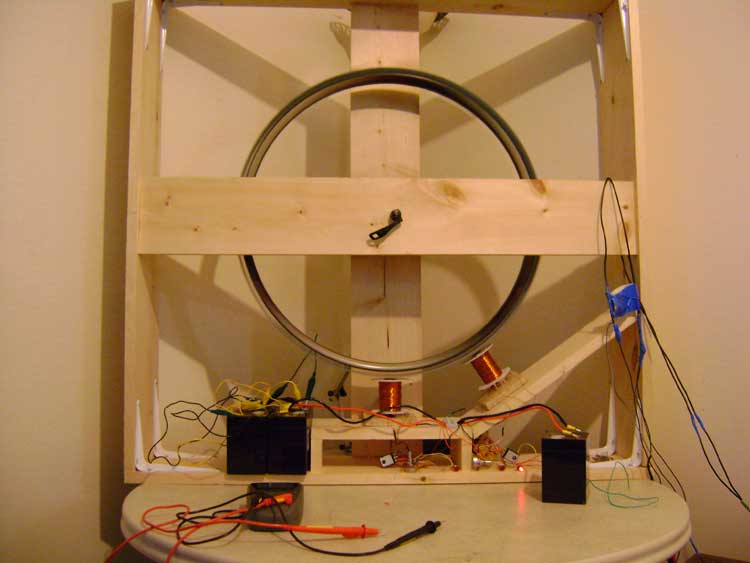
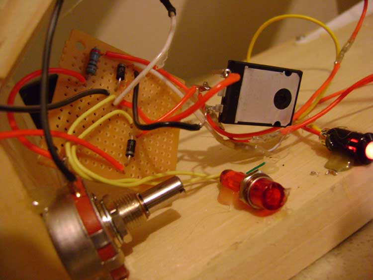
Have done very little to document my progress in building a monopole energizer so here are some really poor quality pics to look at. Must learn to walk before we can run. Added New Pictures! I will be purchasing a decent camcorder/camera very soon. (done!) This is my first shot of my dual monopole energizer. Both are running a separate ciruit with own 2n3055 transistors. Still have pots in the circuit as i have only had this motor running for less than a couple of weeks and have only just set up an oscilliscope. Still have to really learn how to best tune the trigger resistance properly. Will be testing with 1 ohm resistor on secondary output. The two circuits are strung together in parallel. This may or may not be a good idea or arrangemnet as I have seen others using 1 trigger for multiple power coils in a slave/master arrangement. |
 |
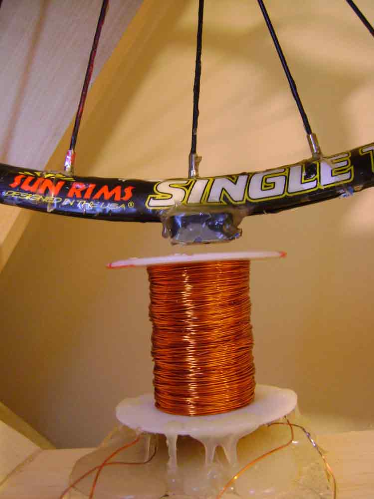
Heres a up close look at one of my coils. I used hot melt glue and fiber glass resin and hardener to create a remarkably strong bond. (cracked alot of fiberglass when pealing off the fiber mesh and duct tape off from previous attempts to secure the magnets down. Now my magnets are completely exposed to the coils on the outside. (much better) Gotta love the hot glue! |
 |
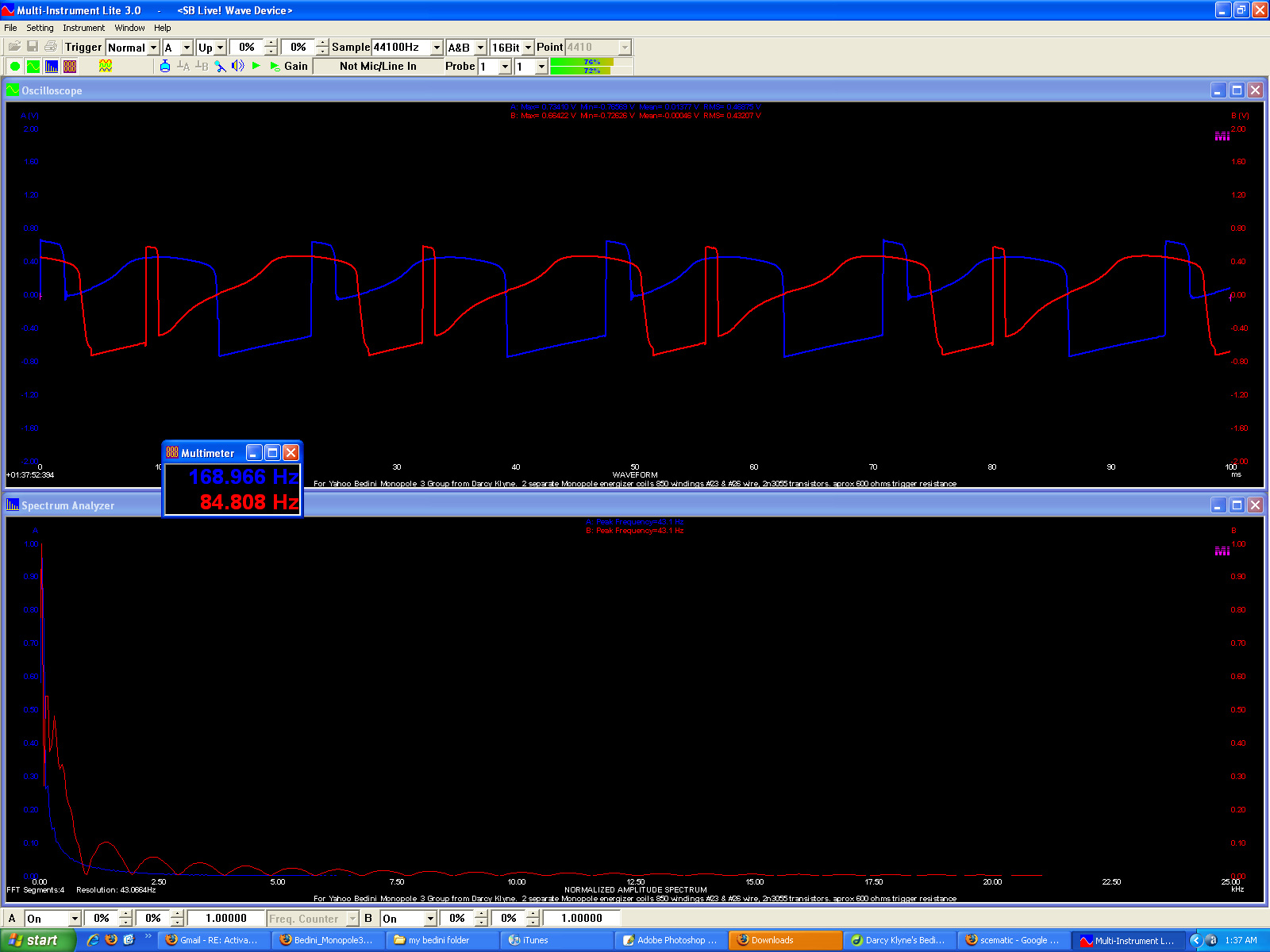
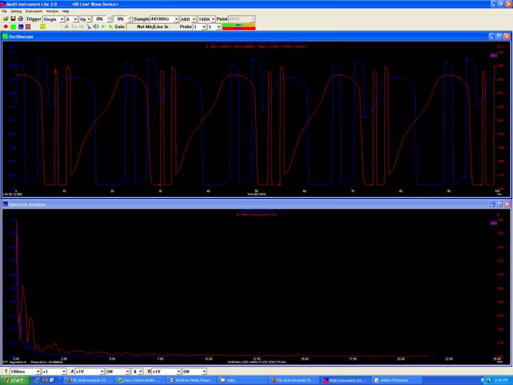
| Just set up Multi-Instrument Pro on computer. Paid and registered the lite version now. | 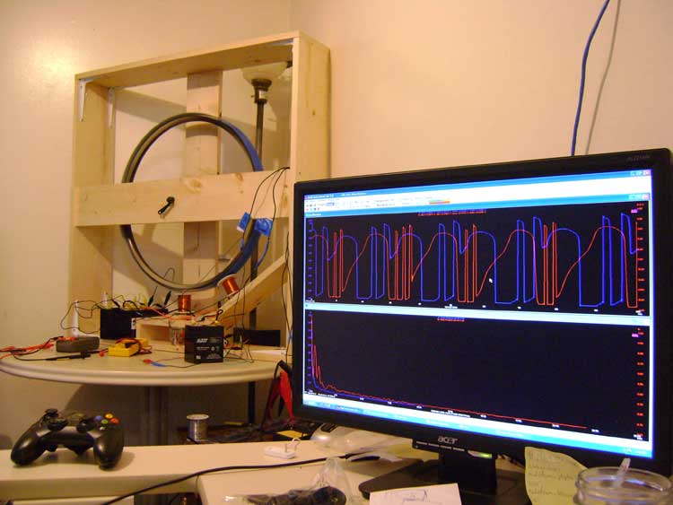 |
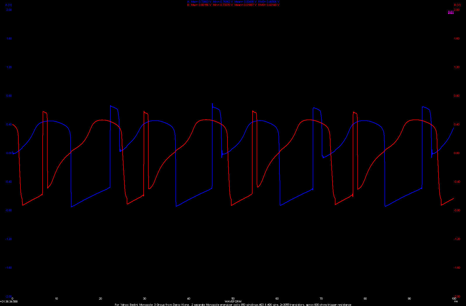
| Made some simple probes using 4 diodes (across ground to L and R channel of your sound cards Line-In input)and a 460ohm resistor to end of probe. Virtins Technology includes instructions for making probes in help menu of program (note: use Line in channel of your sound card and not the microphone as the mic only usually supports 1 input channel and Line in will support 2). Here's a couple shots of the H-wave pattern that appeared for me. I'm basically an electronics novice still and have little experience with Oscilliscopes. I have noticed that B channel drops down lower than A with these readings off the collector.
Calculating on a 100ms scale (based on top image), 4.5 pulses / 100ms = 45 pps 45 pps x 60 = 2700 ppm 16 magnets per revolution 2700 / 16 = 168.75 rpms ( not bad, have had better) I'm using 12v 4.5ah batteries, one of which was providing 250 ma @ 12.32 volts at the time of the top reading. My own thoughts are that 250ma for both coils was pretty effiicient. I know i need to build a capacitive discharge for the output of my circuit. Since joining the yahoo Bedini monopole_3 Group i've discovered that i may be doing a few things improperly. :P I'm still just kind of experimenting at this stage.
|
|
| This one is closer to 184 rpms. 210ma current input @12.24 volts | 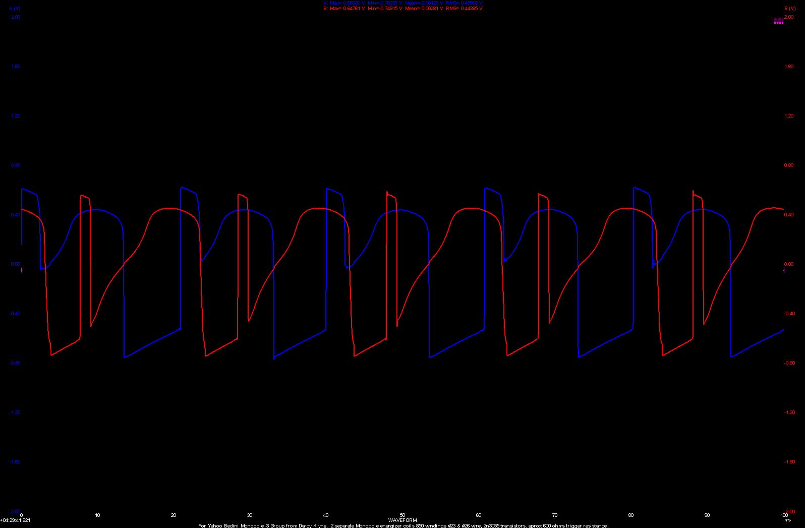 |
Some new MJL21194 Transistors about to go in place of my 2N3055 s . Still tuning and changing componentry so the 1 K Pots are still in the circuit. (good pots) |
 |
Since changing the transistors i've noticed a multiple pulse occuring in both coils, some times three. |
 |
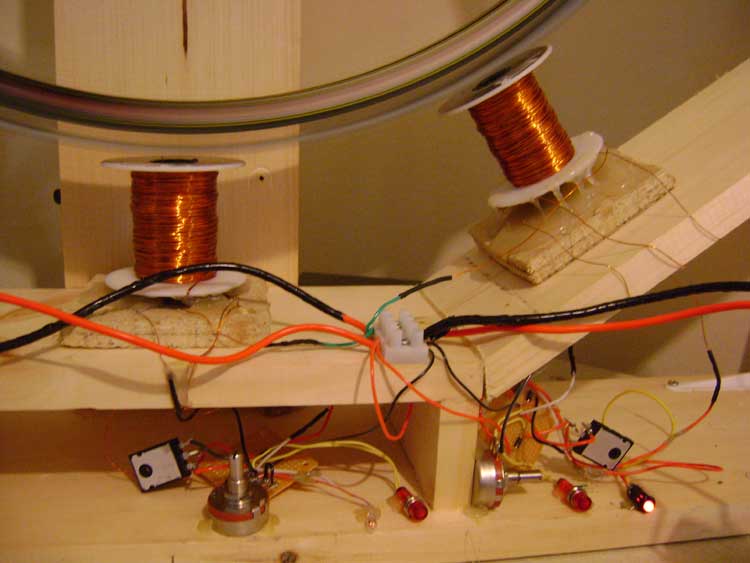
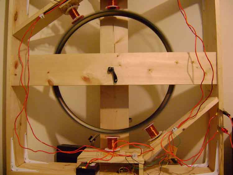
Heres a clearer view of the two circuits bridged together to the same pirmary and secondary batteries. I don't know that this is at all a proper way to set this up, however it does seem to work this way. I am planning on adding more coils. Would also like to set up a proper battery switching system as it is not convienent to be around to monitor primary battery. Replication of a battery charging system being discussed here. I will be trying to develop the same programable system. Had also been considering using a capacitive discharge in front of the secondary (charging) battery banks. Here is a really good discussion as well as some examples of people using a capacitive discharge, as well as why you might want to use one in your monopole replication. |
 |
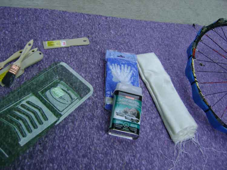
I grew tired of having to repeatedly refasten my magnets. I actually had a near catastrophic situation where my wheel actually knocked a coil right off of the frame. I decided that some fiber cloth, fiberglass resin and hardener were in order to keep things in their place. Edit- Just a note to anyone using fiberglass resin and hardener on their model. If you hot melt glue your magnets on and then paint the rim with fiberglass resin and hardener, that will be sufficient to hold them on from what i've seen. There is no need for anything else on top of the magnets on mine anymore. |
 |
| I did a pretty rough job of layering on a strip of fiberglass on top of the magnets and I made sure to completely coat the entire rim with resin and hardener. Combined with the hotmelt glue that is holding the magnets to the wheel i think i have a very solid mount now. Just one strip of fiberglass doesn't seem to have added too much weight to the rim. (still need to clean up a bit.) | 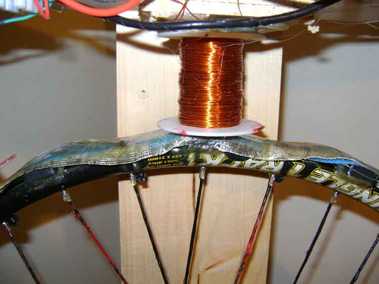 |
Have now added two more coils to the wheel and I'm seeing better charging on the secondary banks now. I'm pleased with my progress, however i need to dial in the proper resistance for each coil while adding more coils to the mix. I feel that efficiency will be compromised until i have all 8 coils running and then tune each one individually with the scope. I hope to have the other four coils on soon. Here is a video of the wheel running with 4 coils. Edit - I really dialed in each circuit with a 1 K pot at the top of the trigger coil of each circuit i tuned it for a combination of best speed vs amp draw. By the time i was done i was running around the 200 ma region for all four coils! That made me happy. |
 |
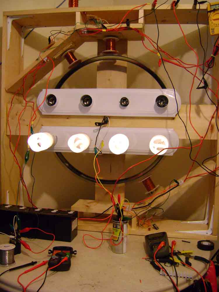
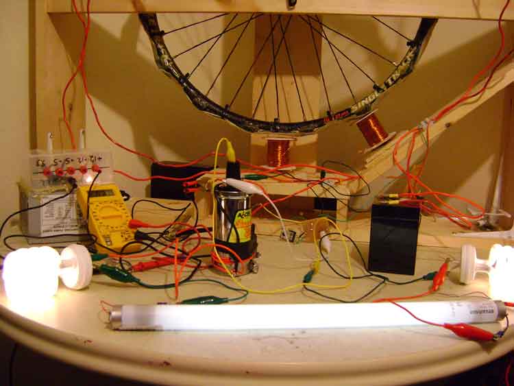
Really having fun now. I've recently been directed to an excellent discussion on the Energetic Forum that was started by Imhotep. Here i've hooked up the coil from Imhotep's Radiant Oscillator to the power coil connection one of the bedini circuits. I have to give the wheel a turn to get it oscillating and then stop it to get the transistor to self oscillate. I'm getting a decent illumination on 2 helicoil 16/20/24watt bulbs and a 15w flourescent wired in series. When i disconnect a lead in the series of bulbs one or more bulbs continues to light! I'm not sure but is that a example of a radiant current flow? Lots to describe, too much so i made another video. I just started with this arrangement and it seems to be giving my secondary battery a better charge than the wheel did on its own. Who knew? Maybe Tesla would have something to say. |
 |
| In case some of you want to try to get your bedini circuit self ocsillating and then hook it up to a ignition coil, this would be one way that works for me. I have to reitterate the fact that my oscillating setup seems to far surpass the radiant charging that the original desgin could produce. I hope John Bedini doesn't mind my borrowing his schematic. If so i will remove it immediately. |  |
Playing around with some new lithium ion 12v batteries that i just made from 2 - Energizer 6volt E-squared non rechargeable lithium ion batteries. They seem to charge up nice and fast on the circuit especially when the ignition coil is running on one of the SSGs. I have wheel running really well now on 3 bifilar coils, two running the wheel and the other pulsing the ignition coil. I am finding a higher amperage here at 1.03 amps, however my charging has gone up considerably. For some reason having the ignition coil pulsing the lights is creating a different type of radiant negative charge than i was dealing with on a straight bedini type wheel. Much more radiant i think. Here is a video of me just messing around with a new setup on modvid.com. Or at Youtube Its not meant to illustrate anything in particular. Maybe a little less talking in the next video. The amp draw while self oscillating compared to when the wheel is pulsing is marginal at best. It would appear that running the wheel is the best solution and produces the most charging on the secondary banks that i've seen so far. Just a note to anyone using fiberglass resin and hardener on their model. If you hot melt glue your magnets on and then paint the rim with fiberglass resin and hardener, that will be sufficient to hold them on from what i've seen. There is no need for anything else on top of the magnets on mine anymore. |
|